HMI Screen Background Colors: Design Intent vs Hardware Tint
HMI screen background colors sit at the center of every operator display: the gray field behind pumps, the alarm red that must never look brown, the live-data blue that must stay distinct from static equipment. When those backgrounds look wrong, the cause is either intentional project design, a corrupted color setting, or hardware that is shifting the entire optical stack. This guide separates those paths and evaluates how solid-color testing with our Screen Test tool exposes each one on industrial panels.
What HMI Screen Background Colors Are Supposed to Do
On a well-designed process HMI, background color is not decoration. Rockwell Automation's Process HMI Style Guide and the ASM Consortium gray-background practice both treat the page field as a low-salience canvas so alarms and live values can own the saturated colors. The practical standard is an unsaturated light gray such as RGB 224,224,224 (#E0E0E0) for well-lit rooms, with darker grays reserved for dim 24/7 consoles. Static equipment interiors often match the background; process lines stay dark gray or black; gradients are discouraged because they fight attention management (Rockwell proces-wp023, Honeywell ASM gray-background paper).
Siemens WinCC Unified exposes the same idea at the object level: background color, border color, and fill pattern are configured per screen object from a palette or RGB picker, including transparent fills when operators must hit a border precisely (Siemens WinCC Unified color docs). Changing a Siemens color scheme therefore means editing the project — not hoping the panel will invent a new gray on its own (XCTimes Siemens color-scheme overview).
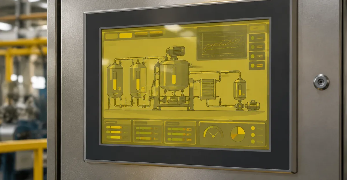
That design intent creates a diagnostic trap. Operators say "the background turned yellow" when three different things may have happened: the engineer shipped a warmer gray, the runtime is stuck on a 16-bit color depth that cannot render the intended silver, or the LCD stack itself aged warm. Maintenance teams then burn a shift chasing palette downloads when the glass is already optically failed — or they order modules when only the project color depth was wrong. Until you put a known RGB field on the glass, you are guessing which of those three is true.
Why Gray Backgrounds Fail in the Field
Gray only works when the panel can still reproduce neutral luminance. Heat, UV, humidity, and continuous backlight duty shift polarizers, optical adhesives, and LED phosphor toward yellow, so the same #E0E0E0 project color reads as cream or brown on an aged unit while a new spare beside it still looks correct (CDTech LCD yellowing, Miqidisplay industrial tint analysis). Alarm contrast collapses next. A Priority-1 red on a yellowed gray background loses the luminance jump the style guide assumed, which is why background-color complaints are safety-adjacent even when nobody changed the project.
HMI Screen Color Problems That Come From Hardware
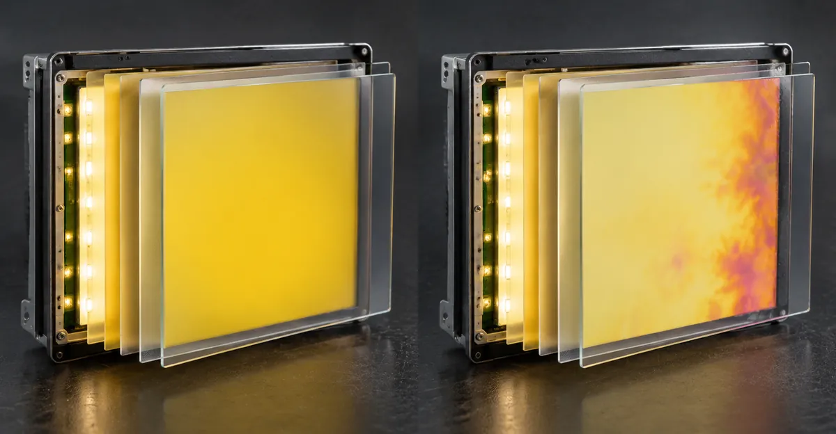
Industrial touch panels share the same failure families as other long-life LCDs, with harsher duty cycles. Yellowing is usually optical-stack aging: iodine polarizers lose efficiency, OCA/OCR adhesives oxidize, blue transmission through color filters drops, and LED phosphor or older CCFL tubes lose blue output so whites warm up (CDTech, Rocktech TFT color problems). Localized yellow near bezels or heat sources often tracks thermal hotspots from CPUs, power stages, or poorly ventilated enclosures rather than a global project setting (HiggsTec industrial touchscreen guide).
Pink-to-orange blotches — nicknamed sunrise on Allen-Bradley PanelView Plus units — behave differently. Field write-ups tie most cases to moisture or washdown intrusion that damages LCD row drivers or the ribbon path between glass and video board. Loose ribbons can flicker with vibration; overtightened bezels can flex the glass. Critically, backlight aging looks even across the whole screen, while sunrise damage looks blotchy with soft natural borders (Industrial Monitor Direct PanelView color troubleshooting). Treating blotches as a FactoryTalk color edit wastes a maintenance window.
Cable and connector faults sit between those extremes. Vibration and temperature cycling loosen LVDS/eDP-style display cables and flex tails. One channel drops first, so the background gains a green, blue, or magenta cast before the image collapses. Intermittent color that changes when you press the bezel or when the machine vibrates is a mechanical signal path problem until proven otherwise (Omega Electronics HMI repair symptoms, HiggsTec). A useful field check is to photograph the same solid red and solid green fields before and after a firm ribbon reseat; if the cast collapses in one cycle, stop ordering LCD glass and stock the correct flex cable instead.
Software Paths That Still Matter
Not every wrong background is a dead polarizer. PanelView Standard terminals expose a runtime palette remap that PanelView Plus does not; Plus colors live as absolute ARGB in FactoryTalk View ME and must be edited on the engineering station (Industrial Monitor Direct PanelView color text methods). TIA Portal projects that inherit a 16-bit color depth can refuse common gray values such as RGB 192,192,192 until runtime color depth is raised to 32-bit (Industrial Monitor Direct TIA color depth). Those are real fixes — but they only apply when solid-color evidence shows the panel can still paint pure white and pure primary colors correctly.
Design Palette vs Panel Failure: The Decision Matrix
Competing pages explain how to pick gray in a style guide or how to replace a yellowed module. They rarely tell a technician which evidence decides the path in the first five minutes on the plant floor. Use this matrix before you open the enclosure.
| What you see | Solid white / gray test | Likely cause | Next action |
|---|---|---|---|
| Whole page warmer than a known-good spare; even cast | White and gray both warm; primaries intact | Backlight / polarizer / adhesive aging | Document photos; plan module swap; check enclosure heat |
| Pink/orange blotches, soft borders | Blotches remain on every solid color | Moisture / row driver / ribbon path | Stop washdown near seals; repair or replace LCD assembly |
| Sudden green, blue, or magenta cast | One primary looks weak or noisy | Display cable or driver channel | Power down; reseat/replace ribbon; retest solids |
| Only some objects wrong; white test looks clean | Solids neutral; project graphics wrong | Palette, color depth, or object properties | Fix in WinCC / FactoryTalk / PanelBuilder; redownload |
| Wrong only at a steep viewing angle | Solids OK head-on | TN viewing-angle behavior or mounting height | Compare IPS vs TN expectations; adjust mount before condemning panel |
| Tint fades after long power-off, returns when hot | Solids worse after thermal soak | Temporary thermal stress vs permanent aging | Repeat white test cold and hot; permanent cast after 48h cool-down means material aging (CDTech thermal recovery) |
The unanswered question most style guides leave hanging is this: your project background is already gray, so how do you know the gray is wrong? Answer it by forcing fields the project never draws — pure white, pure black, and the three primaries. If those look wrong, the panel is lying about every project color, including alarms. If those look right while only the runtime graphics look wrong, stay in the engineering software.
Screenshot traps matter here too. A remote HMI client or VNC session can show correct RGB while the physical glass is yellowed, because the capture path never passes through the aged polarizer. IT tickets that look fine on a remote session are a common false close. Always judge background color problems from the operator's eye distance on the real panel, then photograph the solid-color fields with a phone for the work order and note serial number, firmware, and ambient temperature.
Screen Test Tool Review for HMI Background Color Diagnosis
This section is a first-party evaluation of the ScreenIssues Screen Test tool against HMI background-color work — not a generic "use test patterns" tip. The tool exposes four tabs that map cleanly onto industrial color complaints: Solid Colors, Gradients, Patterns, and Motion, with fullscreen mode, auto-cycle, keyboard stepping, and a brightness slider for low-luminance inspection.
Solid Colors — the primary HMI workflow
| Test field | Hex | What an HMI background problem looks like |
|---|---|---|
| White | #FFFFFF | Uniform yellow/cream cast = optical aging; corner patches = adhesive or heat-edge yellowing |
| Black | #000000 | Bright blotches or glow = backlight bleed or stuck regions; should not show pink sunrise (that appears on lighter fields too) |
| Red | #FF0000 | Dark dots or weak red = subpixel/cable issues that also muddy alarm reds on gray backgrounds |
| Green | #00FF00 | Channel imbalance or cable faults that make "normal running" greens unreliable |
| Blue | #0000FF | Exposes backlight unevenness and cool/warm imbalance operators describe as wrong gray |
| Gray | #808080 | Closest proxy to ASM/Rockwell page backgrounds; banding or brown shift here predicts operator complaints |
For HMI background colors specifically, white then gray is the highest-yield pair. CDTech's industrial yellowing procedure already centers a #FFFFFF full-field check at high brightness; gray adds the page-color the operator actually stares at for hours. Red/green/blue then confirm whether alarm and status hues are still separable once the background is trusted.
Gradients, Patterns, and Motion — when solids are not enough
RGB gradients reveal banding and non-uniform tint that a flat gray can hide — useful when one side of a large PanelView looks warmer after years next to a drive cabinet. Horizontal/vertical lines, grid, checkerboard, and RGB stripe patterns separate line/driver faults from pure background tint: if solids look evenly warm but patterns tear into columns, you are not looking at simple yellowing. Motion blur testing is a negative control for background-color tickets — if the complaint is "the gray looks wrong" and motion is fine while solids are warm, stay on the optical-aging path and do not chase scan-rate myths.
Tool vs HMI built-in diagnostics
| Need | Screen Test tool | Typical HMI built-in diagnostics |
|---|---|---|
| Known RGB full fields | Yes — fixed white/black/RGB/gray | Often limited or buried in OEM service menus |
| Works without OEM software license | Yes — browser on a laptop or panel with HTML runtime | Usually needs OEM service mode or vendor laptop |
| Matches style-guide gray intent | Gray field approximates page background | Rarely includes ASM-style gray patches |
| Separates project graphics from panel | Yes — fields ignore your .MER/.apd artwork | Built-in screens may still use themed colors |
| Offline plant floor use | Needs a browser-capable device or temporary HDMI/USB input | Available on some terminals without network |
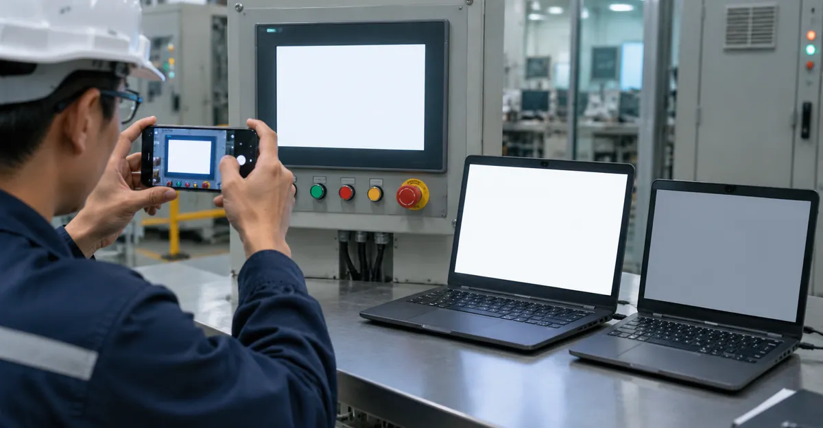
Practical plant-floor method: when the HMI itself cannot open a browser, run Screen Test fullscreen on a maintenance laptop, photograph the six solids as a reference strip, then display the closest full-field screens the OEM provides (or a temporary solid-color popup in a test project). Match laptop reference photos to the panel under the same ambient light; do not dim room lights between shots. That comparison is the exclusive diagnostic step style guides never document, and it prevents expensive wrong LCD spare orders.
Auto-cycle plus phone photos create a warranty package in under two minutes: white, gray, red, green, blue, black, each held long enough to focus. Brightness slider down on black and gray makes subtle yellow patches and backlight edges obvious without opening the enclosure first.
How to Run Background Color Checks on Industrial Panels
- Freeze the narrative. Note whether the cast is uniform or blotchy, sudden or gradual, one terminal or a whole line, and whether alarms still look saturated. Photograph the live process screen once for context only.
- Rule out easy software. Confirm nobody deployed a new color scheme, Night-mode equivalent, or 16-bit runtime depth. On PanelView Standard, check whether Configuration Mode palette slots were remapped; on Plus and WinCC, open the project, not the terminal menus.
- Run solid fields. Use Screen Test or OEM full-field patterns. Spend the longest look on white and gray. If white is clean and only the process page looks wrong, stop and fix the project.
- Cross-check with heat and angle. View head-on and from the operator's normal stance. Power down for a cool period when CDTech-style thermal recovery is in doubt, then retest white before condemning the module.
- Mechanical pass. Only after solids implicate cable or blotchy moisture damage should you power down, inspect seals, and reseat display ribbons. Do not chase bezels on a globally yellowed backlight.
- Decide with the matrix. Even warm white → aging path. Blotchy sunrise → moisture/driver path. Single-channel failure → cable path. Clean solids → software path.
Related consumer and IT display color issues use the same solid-field logic; if you maintain office monitors alongside HMIs, the yellow and pink monitor tint and general monitor color problem guides reuse the white/gray/primary sequence without the industrial style-guide layer.
Fix Paths After the Colors Are Classified
Software and project fixes. Correct object backgrounds and palettes in WinCC Unified, FactoryTalk View ME, or PanelBuilder; raise TIA color depth when gray values will not stick; redownload runtime; verify contrast/brightness on legacy terminals that still expose those knobs. Re-run gray and white solids after the download so you know the glass, not only the project, improved.
Cable and connector fixes. Reseat both ends of the display ribbon, replace damaged flex tails, and confirm strain relief so vibration does not recreate the fault. Retest primaries — a recovered red channel should restore alarm red on gray backgrounds immediately.
Backlight and optical stack. Uniform yellowing from CCFL/LED aging or adhesive yellowing is not calibrated away for long. Temporary color-temperature tweaks buy readability; the durable fix is module or backlight replacement rated for the enclosure temperature and duty cycle (CDTech, Miqidisplay).
Panel replacement triggers. Spreading pink/orange blotches, permanent yellow after cool-down, obsolete spares, or any case where operators can no longer trust alarm colors. Capture solid-color evidence before the unit leaves the cell. For line-type defects that appear during the same investigation, see LCD line issues and colored lines.
When Wrong Background Colors Become a Safety Issue
ASM and Rockwell both assume color is a scarce code: red for high-priority alarms must not also mean "pump running," and the background must stay visually quiet. A yellowed or channel-shifted panel breaks that contract. Operators slow down on alarm acknowledgment, misread state fills, and invent workarounds like walking closer or using a second laptop client. If solid-color testing shows the glass can no longer separate alarm red from the page field, treat the terminal as impaired for safety-critical operation until repaired — the same severity you would assign to an unreadable alarm banner.
Prevention tracks the hardware causes: keep enclosure temperatures inside the module rating, protect washdown seals, avoid overtightening bezels, use filtered power and proper grounding to reduce electrical noise on graphics boards, and standardize HMI style guides so every new project ships the same gray field. Incoming inspection with white and gray solids on spare modules catches batch LED-bin differences before they land on the line (Miqidisplay). Keep a short baseline photo set for each critical terminal after commissioning — white, gray, red — so the next yellowing ticket has a same-panel reference instead of a subjective memory of how the gray used to look.
Conclusion
HMI screen background colors go wrong for design reasons, software configuration reasons, or optical/hardware reasons — and those three need different tools. Style guides explain why gray exists; vendor docs explain how to edit palettes; hardware articles explain yellowing and sunrise blotches. The missing step is forcing known RGB fields so you can tell which story you are in. Run white and gray first, confirm primaries, then choose project edit, cable reseat, or module replacement. Use the Screen Test tool to build that evidence in fullscreen, then keep the photos with the work order so the next technician does not repeat the guesswork.